AC Induction Motor Characterization
Vue d'ensemble
Source: Ali Bazzi, Department of Electrical Engineering, University of Connecticut, Storrs, CT.
The objectives of this experiment are to find the equivalent circuit parameters of a three-phase induction motor using the per-phase equivalent circuit and tests similar to those used in transformer characterization. In electrical engineering, an equivalent circuit (or theoretical circuit) can be determined for a given system. The equivalent circuit retains all characteristics of the original system, and is used as a model to simplify calculations. Another objective is to operate the motor in the linear torque-speed region.
Procédure
1. DC Test
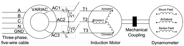
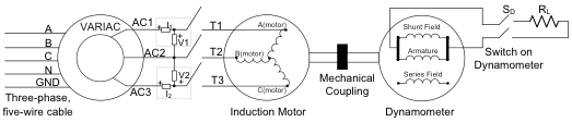
Note that a squirrel-cage induction machine has only stator terminals accessible.
- Turn on the low-power DC power supply and limit the current to 1.8 A.
- Turn the supply off.
- Connect the supply terminals across two of the induction motor terminals (labeled A, B, and C).
- Turn the supply on and record the output voltage and current.
- Repeat for the two other phase combinations.
- Note that the measured resistance is for two ph
Résultats
A common mistake in finding the equivalent circuit parameters of induction machines is to use the three-phase measured power in calculations of the per-phase equivalent circuit, while one third of the power should be used: three phases consume the measured power, and thus, one third of the power is in one phase.
Calculations of the equivalent circuit parameters are similar to those of the transformers, but it is common to split X1 and X2' per the NEM
Applications et Résumé
Three-phase induction machines, especially induction motors, are the workhorses of modern industry. Appropriately characterizing an induction motor provides engineers and technicians with information on the motor's efficiency and torque-speed characteristics. These are essential in determining which motor size and frame best fits an application. Once a motor is characterized and the torque-speed curve is known from equivalent circuit parameters using the tests described, different NEMA fr
Tags
Passer à...
Vidéos de cette collection:

Now Playing
AC Induction Motor Characterization
Electrical Engineering
11.6K Vues

Electrical Safety Precautions and Basic Equipment
Electrical Engineering
144.6K Vues

Characterization of Magnetic Components
Electrical Engineering
15.0K Vues

Introduction to the Power Pole Board
Electrical Engineering
12.4K Vues

DC/DC Boost Converter
Electrical Engineering
56.9K Vues

DC/DC Buck Converter
Electrical Engineering
21.1K Vues

Flyback Converter
Electrical Engineering
13.2K Vues

Single Phase Transformers
Electrical Engineering
20.1K Vues

Single Phase Rectifiers
Electrical Engineering
23.4K Vues

Thyristor Rectifier
Electrical Engineering
17.5K Vues

Single Phase Inverter
Electrical Engineering
17.9K Vues

DC Motors
Electrical Engineering
23.4K Vues

VFD-fed AC Induction Machine
Electrical Engineering
6.9K Vues

AC Synchronous Machine Synchronization
Electrical Engineering
21.6K Vues

AC Synchronous Machine Characterization
Electrical Engineering
14.2K Vues
À PROPOS DE JoVE
Copyright © 2025 MyJoVE Corporation. Tous droits réservés.