JoVE Science Education
Electrical Engineering
A subscription to JoVE is required to view this content.
AC Synchronous Machine Synchronization
Source: Ali Bazzi, Department of Electrical Engineering, University of Connecticut, Storrs, CT.
Three-phase wound-rotor synchronous generators are the main source of electrical power worldwide. They require a prime mover and an exciter in order to generate power. The prime mover can be a turbine spun by fluid (gas or liquid), thus the sources of the fluid can be water running off a dam through a long nozzle, steam from water evaporated using burned coal, etc. Most power plants including coal, nuclear, natural gas, fuel oil, and others utilize synchronous generators.
The objective of this experiment is to understand the concepts of adjusting the voltage and frequency outputs of a three-phase synchronous generator, followed by synchronizing it with the grid. The effects of field current and speed variations on the generator output power are also demonstrated.
1. Prime-Mover Initialization
The prime-mover in this experiment is the dynamometer, which operates as a motor that spins the generator rotor (field).
- Make sure the three-phase disconnect switch, synchronous motor switch, and DC motor switch are all off.
- Check that the VARIAC is at 0%.
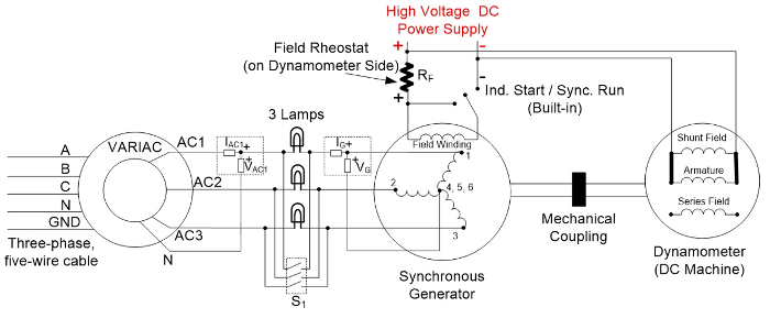
- Wire the VARIAC to the three-phase outlet and connect the setup shown in Fig. 1.
- Use the three-phase switch on the synchronous machine side as "S1."
The desired speed of the prime-mover is set at 1,800 RPM since the synchronous machine has four poles (P) and operates at a frequency f= 60 Hz, thus synchronous speed is 120f/P= 1,800 RPM.
When synchronizing the synchronous machine (generator) to the grid, the machine's prime-mover provides rotation, but a magnetic field on the machine's rotor should be provided. This is achieved using
Synchronous generators are the backbone of electricity generation in power plants worldwide. Synchronizing a generator to the grid has become standard practice and is typically automated by matching the phase sequences, voltage magnitudes, and frequencies of the generator to the grid. Voltage control using the rotor magnetic field is achieved using "exciters," while frequency control is achieved using the speed control of a turbine or prime-mover, providing rotation using steam, wind, water, or other fluids. Frequency co
Skip to...
Videos from this collection:

Now Playing
AC Synchronous Machine Synchronization
Electrical Engineering
21.5K Views

Electrical Safety Precautions and Basic Equipment
Electrical Engineering
144.4K Views

Characterization of Magnetic Components
Electrical Engineering
14.9K Views

Introduction to the Power Pole Board
Electrical Engineering
12.4K Views

DC/DC Boost Converter
Electrical Engineering
56.5K Views

DC/DC Buck Converter
Electrical Engineering
21.0K Views

Flyback Converter
Electrical Engineering
13.2K Views

Single Phase Transformers
Electrical Engineering
20.1K Views

Single Phase Rectifiers
Electrical Engineering
23.3K Views

Thyristor Rectifier
Electrical Engineering
17.4K Views

Single Phase Inverter
Electrical Engineering
17.9K Views

DC Motors
Electrical Engineering
23.3K Views

AC Induction Motor Characterization
Electrical Engineering
11.6K Views

VFD-fed AC Induction Machine
Electrical Engineering
6.9K Views

AC Synchronous Machine Characterization
Electrical Engineering
14.2K Views
ISSN 2578-370X
Copyright © 2025 MyJoVE Corporation. All rights reserved
We use cookies to enhance your experience on our website.
By continuing to use our website or clicking “Continue”, you are agreeing to accept our cookies.