Source: Yong P. Chen, PhD, Department of Physics & Astronomy, College of Science, Purdue University, West Lafayette, IN
This experiment will use inductive coils to demonstrate the concept of inductor and inductance. Magnetic induction will be demonstrated using a rod magnet inserted into or extracted away from the core of a coil to induce a transient electromotive force (emf) voltage in the coil, measured by a voltmeter. This experiment will also demonstrate the mutual inductance between two coils, where turning on or off a current flowing in a coil can induce an emf voltage in a second coil nearby. Finally, the experiment will demonstrate the self-inductance of a coil, when switching a current off induces an emf to light up a light bulb connected in parallel with the coil.
Procedimento
1. Magnetic Induction
Obtain a solenoid coil (with a hollow core) and a rod magnet (with its North and South poles labeled).
Obtain an analogue bipolar ammeter with an indicator needle. The needle is nominally at the middle position at zero reading, and will deflect to the right or left depending on the direction of current flow (positive reading means the current flows from the positive terminal to and negative terminal inside the ammeter).
Connect the two ends of the solenoid to the "
Log in or to access full content. Learn more about your institution’s access to JoVE content here
Resultados
Representative results for what may be observed on the ammeter reading for Sections 1 and 2 (setups in Figures 1 and 2) are summarized in Tables 1 and 2 below.
Procedure Step
Orientation of Rod Magnet
Motion of Magnet
Reading on the ammeter
1.4
South-North (North is
Log in or to access full content. Learn more about your institution’s access to JoVE content here
Aplicação e Resumo
In this experiment, we have demonstrated how changing a magnetic field (by moving a magnet) induces a current in a coil, and also how changing the current in the coil induces current in another coil (mutual induction). We also demonstrated that changing the current in a coil induces a voltage and current in the same coil (self-induction).
Inductors (typically in the form of coils) are commonly used in many circuit applications, such as to store magnetic energy when a steady state current flows
Log in or to access full content. Learn more about your institution’s access to JoVE content here
Obtain a solenoid coil (with a hollow core) and a rod magnet (with its North and South poles labeled).
Obtain an analogue bipolar ammeter with an indicator needle. The needle is nominally at the middle position at zero reading, and will deflect to the right or left depending on the direction of current flow (positive reading means the current flows from the positive terminal to and negative terminal inside the ammeter).
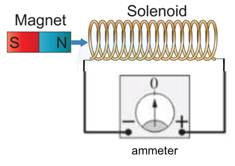
Connect the two ends of the solenoid to the "+" and "−" terminals of the ammeter, as in Figure 1. The connection can be made with cables with clamps or banana plugs into receiving ports on the instruments.
Bring the rod magnet closer to the coil and insert its north end into its core, as shown in Figure 1. Observe the ammeter and record the sign of its reading. For all observations to be conducted in the following, always record both the sign and the approximate magnitude of the reading.
Extract the magnet back out of the coil, and observe the reading on the ammeter.
With the rod magnet far away from the coil, flip it over and now move the South end closer to the coil. Insert the South end into the core of the coil, and observe the reading on the ammeter.
Extract the magnet back out of the coil again, and observe the reading on the ammeter.
Repeat steps 1.6 and 1.7 above again (insert and extract South pole of the magnet) but with a slower and then a faster speed, and observe and compare the reading on the ammeter.
Figure 1: Diagram showing a magnet moving toward/away from a coil to induce a current in the coil (magnetic induction).
2. Mutual Inductance
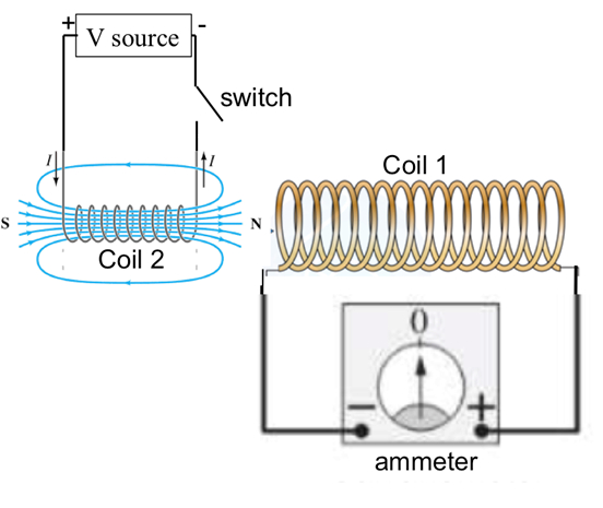
Obtain a second solenoid coil (referred to as coil #2), and bring it close to the first coil (referred as coil #1) as shown in Figure 2. The two coils are aligned approximately along a common axis.
Connect the two ends of coil #2 to a DC voltage source with a switch, as shown in Figure 2. Coil #1 is still connected to the analogue ammeter.
With the switch open, set the voltage source to +2 V, then close the switch to allow a current to flow in the coil #2, and observe the reading on the ammeter connected to coil #1 when the switch is turned on.
Now open the switch, and observe the reading on the ammeter.
Set the voltage source to −2 V (or alternatively, swap the two wires connected to the plus and minus terminals of the voltage source to reverse the sign of the voltage and current to be applied to coil #1), repeat steps 2.3 (switch on) and 2.4 (switch off), and observe the ammeter connected to coil #1.
Now insert coil #2 into the core of coil #1 as fully as possible, repeat the above step 2.5, and observe the reading on the ammeter connected to coil #1.
Figure 2: Diagram showing that a current switching on or off in a coil would induce current in another nearby coil (mutual induction).
3. Self-inductance
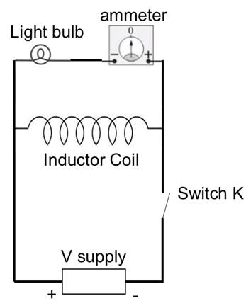
Obtain a light bulb and connect it in series with the ammeter, then connect the combination to coil #2 in parallel with the volt supply, as shown in Figure 3. The voltage on the volt supply is set to be 1 V.
Close the switch to let the current flow through the coil. The light bulb should be dim because the coil has a much smaller resistance than the light bulb, and most of the current will flow through the coil.
Open the switch so that the volt supply is disconnected from the rest of the circuit, and observe the light bulb and the ammeter reading when the switch is just opened.
Figure 3: Diagram showing a circuit to demonstrate self-induction, where tuning off current in a coil induces a transient voltage and current in a light bulb connected to it.