A subscription to JoVE is required to view this content. Sign in or start your free trial.
Method Article
Placement of Extracranial Stimulating Electrodes and Measurement of Cerebral Blood Flow and Intracranial Electrical Fields in Anesthetized Mice
In This Article
Summary
We describe a protocol for assessing dose-response curves for extracranial stimulation in terms of brain electrical field measurements and a relevant biomarker-cerebral blood flow. Since this protocol involves invasive electrode placement into the brain, general anesthesia is needed, with spontaneous breathing preferred rather than controlled respirations.
Abstract
The detection of cerebral blood flow (CBF) responses to various forms of neuronal activation is critical for understanding dynamic brain function and variations in the substrate supply to the brain. This paper describes a protocol for measuring CBF responses to transcranial alternating current stimulation (tACS). Dose-response curves are estimated both from the CBF change occurring with tACS (mA) and from the intracranial electric field (mV/mm). We estimate the intracranial electrical field based on the different amplitudes measured by glass microelectrodes within each side of the brain. In this paper, we describe the experimental setup, which involves using either bilateral laser Doppler (LD) probes or laser speckle imaging (LSI) to measure the CBF; as a result, this setup requires anesthesia for the electrode placement and stability. We present a correlation between the CBF response and the current as a function of age, showing a significantly larger response at higher currents (1.5 mA and 2.0 mA) in young control animals (12-14 weeks) compared to older animals (28-32 weeks) (p < 0.005 difference). We also demonstrate a significant CBF response at electrical field strengths <5 mV/mm, which is an important consideration for eventual human studies. These CBF responses are also strongly influenced by the use of anesthesia compared to awake animals, the respiration control (i.e., intubated vs. spontaneous breathing), systemic factors (i.e., CO2), and local conduction within the blood vessels, which is mediated by pericytes and endothelial cells. Likewise, more detailed imaging/recording techniques may limit the field size from the entire brain to only a small region. We describe the use of extracranial electrodes for applying tACS stimulation, including both homemade and commercial electrode designs for rodents, the concurrent measurement of the CBF and intracranial electrical field using bilateral glass DC recording electrodes, and the imaging approaches. We are currently applying these techniques to implement a closed-loop format for augmenting the CBF in animal models of Alzheimer's disease and stroke.
Introduction
Transcranial electrical stimulation (tES; with sine wave stimulation, tACS) is a common, external, non-invasive approach to brain neuromodulation1,2. Previously, we hypothesized that at certain doses, tES (and particularly tACS) may increase the cerebral blood flow (CBF) in the underlying brain regions3. Further, a dose-response relationship may exist between either the external current applied or the intracranial electrical field and the resulting CBF responses. However, most clinical stimulation protocols have focused on a maximal comfortable skin level of stimulation (i.e., ~ 2 mA) for scheduled periods of time (i.e., 30-45 min) as a treatment protocol4,5. In rodents, it is possible to use invasive, extracranial brain electrodes applied directly to the skull to investigate the electrical fields in the brain induced by tES6. Hence, the goal of this approach is to determine the effects of the intensity of tACS at relevant frequencies on CBF changes in terms of the dose-response relationship. This dose-response curve is based on a short-term physiological biomarker-direct measurements of the CBF-in relation to the electrical field imposed on the brain3. We have previously shown that, at larger amplitudes, typically beyond the range of electrical fields within the brain induced by tACS clinically, there is a near-linear correlation between the induced electrical field and the CBF in the cortex3. However, smaller-field stimulation (i.e., 1-5 mV/mm intensity) may be more relevant and feasible for use in humans; hence, we have modified our techniques to detect smaller CBF changes.
This paper describes a protocol to analyze the effects of lower-field strength tES alternating sine currents (tACS) on CBF (i.e., 0.5-2.0 mA current, 1-5 mV/mm electrical field), which can be tolerated by awake rodents5. This protocol involves the use of novel laser speckle imaging during tACS, as well as dual intracranial glass electrodes, to determine both the spread of active tACS within the brain (as monitored by the CBF) and the intracranial electrical field intensity, which is shown both as a diagram and an actual experimental photograph (Figure 1). There are many possible physiological effects of tES within the brain, including direct neuronal modulation, neural plasticity, and astrocyte activation7,8. Though CBF has been measured with tDCS9,10, these measurements were slow, indirect, and insufficient for assessing the dose-response function in the brain. Therefore, by using appropriate short-term biomarkers (i.e., CBF, electrical fields) and rapid on/off sequences of tACS, we can now estimate the dose-response function more accurately. Further, we can apply different techniques to measure the CBF, including both focal laser Doppler probes (LD) and laser speckle imaging (LSI) with defined regions of interest.

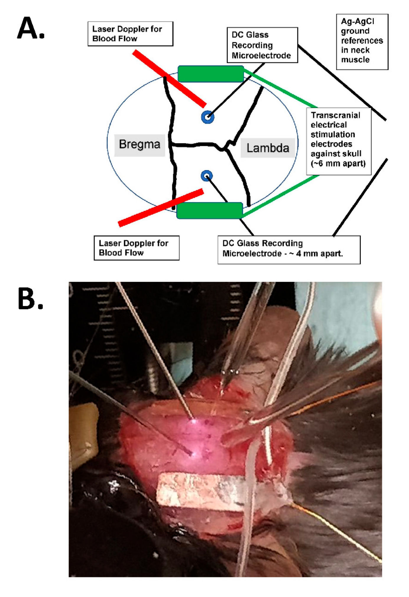
Figure 1: Transcranial stimulation diagram and photographic example. (A) Diagram of the transcranial stimulation setup. The diagram shows a mouse skull with coronal and sagittal sutures. The transcranial electrodes are placed laterally and symmetrically on the skull and are mounted with surgical glue and conductive paste between the electrodes and the skull. These electrodes are connected to a human-compatible, constant-current stimulation device, which can specify the frequency, amplitude, and duration of stimulation. For the assessment of intracranial electrical fields, bilateral glass electrodes (~2 MΩ) are placed in the cerebral cortex (i.e., within 1 mm of the inner aspect of the skull through small burr holes), and these are sealed with mineral oil and have AgCl grounds in the neck muscle (shown as larger wires in the center buried into the subcutaneous neck tissue). These glass electrodes are connected to a DC amplifier, and their outputs are recorded through a digitizer with at least four channels. Bilateral laser Doppler probes are also placed on the skull for recordings. The entire skull is also imaged with either a laser speckle imaging device or a high-resolution (at least 1,024 x 1,024 pixels, 12-14 bit pixel depth) cooled camera for intrinsic optical signal detection. The hemoglobin isosbestic frequency is typically chosen (i.e., 562 nm) for illumination for blood flow imaging. (B) A close-up image of an actual experiment, showing the bilateral laser Doppler probes (to the left), the (bilateral) intracranial glass recording microelectrodes placed through the burr holes, and with the tACS stimulating electrodes laterally. Abbreviation: tACS = transcranial alternating current stimulation. Please click here to view a larger version of this figure.
As a way of assessing the mechanisms, we can also interrogate interactions with other physiological processes that also alter the CBF, such as K+-induced spreading depolarization11. Further, rather than scheduled sessions at regular times, it is also possible to develop a closed-loop system based on additional biomarkers for a variety of diseases, as has been proposed for epilepsy treatment12 (i.e., clinical Neuropace devices). For example, closed-loop brain stimulation for Parkinson's disease is commonly based on the intrinsic, abnormal local field potentials (LFPs) intrinsic to this disease in the absence of sufficient dopamine (typically β-band LFPs)13.
Protocol
All the animal procedures were approved by the Institutional Animal Care and Use Committee at Duke University or the equivalent local authority regulating research involving animals. See the Table of Materials for details about all the materials, instruments, and equipment used in this protocol.
1. Instrument preparation
- Make sure that all the required items and surgical instruments are in place (Figure 2): scalp cleaning solution (alcohol pads), tape, forceps, scissors, and a drill for placing the small (0.5 mm) burr holes.
- Prepare the extracranial surface electrodes for skull application, and make sure any surgical glue has been cleaned from them if they have been used previously.
- Verify the impedance of these tACS electrodes directly before applying them to the skull. For this, use the built-in measurement function of the tACS stimulator with both electrodes placed in a saline bath.
NOTE: The preferred impedance is <5 KΩ per electrode pair to allow sufficient current to be passed across the skull. The stimulator device checks the impedance prior to delivering constant-current pulses and gives the value directly.

Figure 2: A photograph of the required instrumentation, including dissecting instruments and scissors, for preparing the extracranial stimulation. 1. Micro dissecting scissors, 11.5 cm; 2. Forceps, 11.5 cm, slight curve, serrated; 3. Dumont #7 forceps, curved; 4. Dumont #5 forceps; 5. Micro curette, 13 cm; 6. Q-tips; 7. Surgical tape; 8. Alcohol pads. Please click here to view a larger version of this figure.
2. Preparation of the animal for surgery
NOTE: For these experiments, we used 14 C57BL/6 control mice between 12 weeks and 33 weeks of age, of which five were male and nine were female.
- Anesthetize the animal in an induction chamber with isoflurane in 30% O2 at ~1.5 L/min, with ~4% initially to induce and ~1.25%-1.5% to maintain at a level of anesthesia with spontaneous breathing and sufficient to eliminate the tail pinch response.
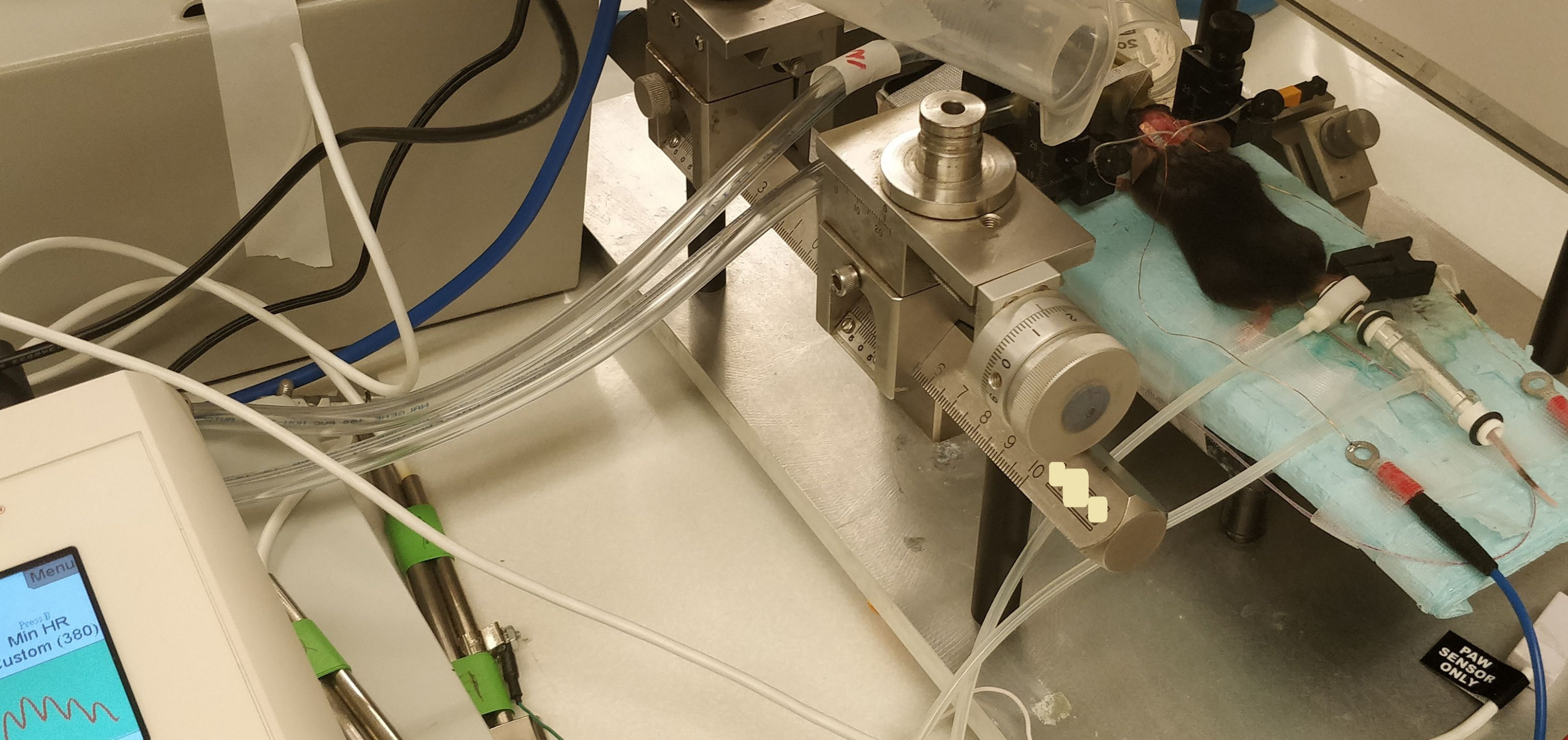
- Transfer the animal to the stereotaxic frame after induction, and then secure the head into the nose cone and ear bars for the subsequent electrode application and burr hole procedure (Figure 1 and Figure 3).
- Connect the nose cone of the stereotaxic frame to the vaporizer via an inlet and to an outlet to remove any isoflurane residual through a scavenger system (e.g., charcoal or a vacuum). Make sure there are no air leaks from the nose cone, both to maintain the anesthesia level with the isofluorane and to prevent accidental leakage into the room air (Figure 3).
- Check the position of the mouse in the stereotaxic frame, including the position of the nose cone, to allow spontaneous respiration without intubation, as well as appropriate anesthesia recovery and scavenging to protect the research personnel (Figure 3).
- Place the probes for measuring the pulse, pulse oxygen saturation (pulse OX), blood pressure, and temperature on the animal; ensure that the minimum pulse oxygenation is 90% and the pulse is >450/min (the alarm lower limit is shown as 380 pulses/min). Record these parameters during the procedure at regular intervals or continuously, depending on the recording system (Figure 3).
- Prior to starting the procedure, check the level of sedation of the animal using (for example) a toe pinch to check the reflexes. If there is no reflex, then the level of sedation is optimal, as long as the animal maintains spontaneous respiration and adequate pulse oxygenation. If there is a reflex, increase the delivery of isoflurane to deepen the level of the anesthesia, and then recheck the reflex. Continuously observe and monitor the respiratory frequency of the animal, and adjust the isoflurane delivery accordingly.
- Shave the scalp hair or remove the hair with depilatory cream (clean the residual cream with alcohol pad passages).
- Apply eye ointment, and then aseptically clean the scalp with three passages of iodine and alcohol prior to excision using scissors.

Figure 3: An image of the animal in the stereotactic frame, with the skull exposed and only the tACS stimulator electrodes in place (prior to the burr hole placement). Note the blood pressure device around the tail and the pulse oximeter on the paw, with the reading on the left. There are scavenging tubes for the isoflurane around the nose cone. Abbreviation: tACS = transcranial alternating current stimulation. Please click here to view a larger version of this figure.
3. Surgical procedure: Applying the stimulating electrodes and making the burr holes
- For a terminal study, remove the scalp using surgical scissors, and expose the skull ~3 mm from the lambdoid suture caudally and ~3 mm frontal to the bregma to expose part of the posterior frontal suture. Excise the scalp parietally to expose the initial part of the temporal muscle on both sides (Figure 3).
- Remove any residual subcutaneous connective tissues so that the skull is clean and dry for the application of the stimulating electrodes.
- Apply conductive gel or paste to the side of the electrodes that will be in contact with the skull, and secure the electrodes with surgical superglue around the edge at intermittent spots.
NOTE: Do not allow the conducting gel to interfere with the surgical superglue in order to allow a better bond to the skull surface. The outer surface of the electrodes can also be insulated (from the scalp if this is closed during a survival surgery) using surgical superglue. - Use either commercial flat electrodes, or create in-house electrodes using insulated wire with a diameter of 100 µm (soldered to the plate) and a 1 mm x 3 mm flexible, insulated (on one surface) copper plate cut according to the size of the skull.
- Apply lidocaine paste on the temporal muscle and scalp on both sides without disturbing the electrodes to reduce the muscle and peripheral nerve activation.
- Once the extracranial stimulating electrodes are in place 4 mm laterally to each side of the skull (between the bregma and lambda), drill two 0.5 mm burr holes for the glass electrodes 2 mm on each side of the midline, 4 mm apart from each other, orthogonal to the sagittal suture (Figure 1). Fill these burr holes with sterile mineral oil to prevent current ingress into the skull from the extracranial electrodes.
- If desired for a particular experiment to induce spreading depression (i.e., potassium-induced spreading depression [K+-SD]), add, on the right side of the skull, a third 0.5 mm burr hole ~1.5 mm rostral to the coronal suture and ~1 mm lateral to the posterior frontal suture. Fill this burr hole with saline for later 1 M KCl application to induce K+-SD.
- Test the impedance of the extracranial stimulating electrodes both prior to the burr hole placement (and compared to the same electrodes placed in a saline bath) and after the burr hole placement to verify that the burr holes do not interfere with the current flow into the brain (i.e., ensure that the resistance is unchanged).
NOTE: The impedance measurement is provided directly by the stimulating device. Generally, we have found the overall system impedance (i.e., from the extracranial electrodes across the skull/brain pathway, typically ~3 KΩ) to be relatively constant regardless of the burr holes and glass microelectrodes, indicating that there is minimal current leakage directly into the brain through the burr holes. - Place the chronic transcranial stimulation electrodes for chronic stimulation in a similar fashion. In this case, insulate the outer surface of the electrodes, close the scalp, and either tunnel the insulated wires out through the scalp or route them into a fixed head stage mounted to the skull.
4. Physiological procedure
- Commence with the physiological aspects of the experiment, once the animal is fully prepared for the non-survival, physiological experiment. Maintain the anesthesia level sufficient for both spontaneous respiration and adequate pulse Ox, respiratory, and pulse levels.
- Measure the CBF resulting from the extracranial stimulation by one of the following two methods.
- Place the mouse under a laser speckle imaging device with or without intracranial recording electrodes to measure the intracranial electrical field during stimulation episodes (Figure 3).
- Transfer the animal to a physiological preparation for the placement of bilateral laser Doppler probes and intracranial electrodes to measure the intracranial electrical field during stimulation episodes (Figure 1).
5. Placement of bilateral laser Doppler and glass electrodes
- Transfer the animal to a microscope stage for the application of bilateral laser Doppler probes. Place the probes on the top of the skull surface between the bilateral burr holes and the coronal suture (Figure 1).
- Fill pulled glass microelectrodes (~0.1 µM, 2-6 MΩ impedance) with 0.2 M NaCl, and place them using a micromanipulator into the two burr holes placed laterally to the sagittal suture3,14 (Figure 1).
NOTE: These burr holes are between the two symmetrical extracranial stimulation electrodes (Figure 1). - Once inserted into the brain, ensure these glass microelectrodes are ~1 mm within the cerebral cortex. Perform depth profiles at various symmetrical depths. Refill the burr holes with sterile mineral oil to insulate this pathway for current flow.
6. Stimulation procedure and measurement of the intensity of the transcranial alternating current stimulation (tACS) or transcranial direct current stimulation (tDCS)
- Record continuous data from the dual laser Doppler probes on the skull and the two intracranial microelectrode outputs (recorded using a DC amplifier with headstages) using a digitizing system and software with at least four channels (at a sampling rate of 1 KHz). Once all the values have been recorded over a sufficiently stable baseline duration (i.e., >10 min), test the extracranial stimulation.
NOTE: Figure 4 shows an example of the four channels with the two intracranial recording electrodes in the upper channels and the CBF response in the lower channels. - Apply brief periods of on/off stimulation at various amplitudes (i.e., 20-30 s, 0.5-2.0 mA, in the tolerable range) to obtain a clear baseline before and after stimulation (Figure 4). Apply the stimulation between the two skull tACS electrodes on either side (Figure 1) using a commercial, human-compatible stimulating device that delivers a constant current.
- Closely observe the mouse for muscle twitches or other responses to the tACS, such as a change in the pulse or respiration, to create an upper limit of tolerability (generally ~2 mA).
- Continue to monitor the impedance across the electrodes with stimulation epochs to ensure this is constant.
- Add a small amount (2-3 µL) of 1 M KCl to the anterior burr hole14 to induce spontaneous K+-SD events. These generate a large CBF response and interactions between the K+-SD-induced CBF response and the CBF response. Estimate the tACS CBF response, applying the tACS stimulation both before and after the occurrence of the SD.
- At the end of the experiment, perform euthanasia through an overdose of isoflurane (5%) and then decapitate once the respirations and heartbeats have ceased.

Figure 4: Data showing four channels of raw data in response to low-intensity tACS. The data are arranged with the upper two rows as the intracranial, direct DC electrical recordings (labeled as Input 1 [IN0] and input 2 [IN1]) and the lower two rows as the bilateral laser Doppler recordings of the cerebral blood flow. Note that the responses are asymmetrical between the right (upper) and left (lower) electrical and cerebral blood flow traces. (A) A small response (16% increase in blood flow) in response to a 1.2 mV/mm 20 s stimulus (0.75 mA). (B) A larger response (21% increase in blood flow) in response to a 1.4 mV/mm stimulus (1.0 mA). Abbreviation: tACS = transcranial alternating current stimulation. Please click here to view a larger version of this figure.
7. Calculation of the electrical field
- Measure the difference in the output from the two intracranial electrodes using the difference in the half-wave (one cycle) of the two sine waves recorded (the upper two traces in Figure 4). Divide this difference (mV) by the distance between the two electrodes (mm, here ~4 mm but directly measured in each case) to arrive at the field strength (mV/mm)3,6.
Results
Representative results are shown in Figure 4, Figure 5, and Figure 6. Figure 4 shows an example of the four channels with the two intracranial recording electrodes on the upper channels and the CBF responses on the lower channels. The tACS is symmetrical across the skull, but generally, the intracranial field response is slightly asymmetrical for applied AC currents, with one side showing a larger respo...
Discussion
This protocol focuses on the in vivo, anesthetized measurement of the CBF response as a biomarker to estimate the brain response to tES14. Longer-term biomarkers of the tES response include histological treatment effects, such as the prevention of or changes in amyloid plaque formation (i.e., with gamma stimulation at 40 Hz in several AD models)16,17,18,19, but ...
Disclosures
The authors have no conflicts of interest to declare.
Acknowledgements
This study was supported by the following grants (to D.A.T.): NIA RO1 AG074999, NIA R21AG051103, VA I21RX002223, and VA I21 BX003023.
Materials
| Name | Company | Catalog Number | Comments |
| Alcohol pads | HenryShein | 112-6131 | |
| Baby mineral oil | Johnson & Johnson | ||
| BD 1 mL syringe | Becton Dikinson | REF 305699 | |
| C3 Flat Surface Electrodes | Neuronexus | ||
| C57BI mice | from NIH colonies | ||
| Copper skull electrods | In house preparation | ||
| Digidata 1440, Clampex | Axon Instruments | ||
| Dumont #5 forceps | FST | #5 | |
| Dumont #7 forceps curved | Dumont | RS-5047 | |
| Eye ointment | Major | LubiFresh P.M. NDC-0904-6488-38 | |
| Flaming/Brown micropipette puller | Sutter instrument Co. | Model P-87 | |
| Forceps 11.5 cm slight curve serrated | Roboz | RS-8254 | |
| Intramedic needle 23 G | Becton Dikinson | REF 427565 | |
| KCl 1 M | In house preparation | ||
| Laser Doppler Probes | Moor Instruments | 0.46 mm laser doppler probes | |
| Laser Speckle Imaging Device | RWD | RFLSI-ZW | |
| Micro curette 13 cm | FST | 10080-05 | |
| Micro Dissecting Scissors, 11.5 cm | Roboz | RS-5914 | |
| Mouse anesthesia fixation | Stoelting | ||
| Neuroconn-DS | Neurocare | DC-Stimulator Plus | |
| PhysioSuite Monitoring | Kent Scientific | ||
| Q-tips | Fisherbrand | 22363167 | |
| Saline 0.9% NaCl solution | Baxter | 281322 | |
| Sensicam QE | PCO Instruments | ||
| Software | Axon Instruments Clampex | ||
| Surgical glue | Covetrus | 31477 | |
| Surgical tape | 3M Transpore | T9784 |
References
- Bestmann, S., Walsh, V. Transcranial electrical stimulation. Current Biology. 27 (23), R1258-R1262 (2017).
- Bikson, M., et al. Rigor and reproducibility in research with transcranial electrical stimulation: An NIMH-sponsored workshop. Brain Stimulation. 11 (3), 465-480 (2018).
- Turner, D. A., Degan, S., Galeffi, F., Schmidt, S., Peterchev, A. V. Rapid, dose-dependent enhancement of cerebral blood flow by transcranial AC stimulation in mouse. Brain Stimulation. 14 (1), 80-87 (2020).
- Shah, S., Chhatbar, P. Y., Feld, J. A., Feng, W. Integrating tDCS into routine inpatient rehabilitation practice to boost post-stroke recovery. Brain Stimulation. 13 (4), 953-954 (2020).
- Voroslakos, M., et al. Direct effects of transcranial electric stimulation on brain circuits in rats and humans. Nature Communications. 9 (1), 483 (2018).
- Alekseichuk, I., Mantell, K., Shirinpour, S., Opitz, A. Comparative modeling of transcranial magnetic and electric stimulation in mouse, monkey, and human. Neuroimage. 194, 136-148 (2019).
- Tavakoli, A. V., Yun, K. Transcranial alternating current stimulation (tACS) mechanisms and protocols. Frontiers in Cellular Neuroscience. 11, 214 (2017).
- Yavari, F., Jamil, A., Mosayebi Samani, M., Vidor, L. P., Nitsche, M. A. Basic and functional effects of transcranial electrical stimulation (tES)-An introduction. Neuroscience and Biobehavioral Reviews. 85, 81-92 (2018).
- Wachter, D., et al. Transcranial direct current stimulation induces polarity-specific changes of cortical blood perfusion in the rat. Experimental Neurology. 227 (2), 322-327 (2011).
- Han, C. H., et al. Hemodynamic responses in rat brain during transcranial direct current stimulation: A functional near-infrared spectroscopy study. Biomedical Optics Express. 5 (6), 1812-1821 (2014).
- Ayata, C., Lauritzen, M. Spreading depression, spreading depolarizations, and the cerebral vasculature. Physiological Reviews. 95 (3), 953-993 (2015).
- Berenyi, A., Belluscio, M., Mao, D., Buzsaki, G. Closed-loop control of epilepsy by transcranial electrical stimulation. Science. 337 (6095), 735-737 (2012).
- Hoang, K. B., Cassar, I. R., Grill, W. M., Turner, D. A. Biomarkers and stimulation algorithms for adaptive brain stimulation. Frontiers in Neuroscience. 11, 564 (2017).
- Turner, D., A, D. S., Hoffmann, U., Galleffi, F., Colton, C. A. CVN-AD Alzheimer's mice show premature reduction in neurovascular coupling in response to spreading depression and anoxia compared to aged controls. Alzheimer's and Dementia. 17 (7), 1109-1120 (2021).
- Colton, C. A., et al. mNos2 deletion and human NOS2 replacement in Alzheimer disease models. Journal of Neuropathology and Experimental Neurology. 73 (8), 752-769 (2014).
- Castano-Prat, P., et al. Altered slow (<1 Hz) and fast (beta and gamma) neocortical oscillations in the 3xTg-AD mouse model of Alzheimer's disease under anesthesia. Neurobiology of Aging. 79, 142-151 (2019).
- Etter, G., et al. Optogenetic gamma stimulation rescues memory impairments in an Alzheimer's disease mouse model. Nature Communications. 10 (1), 5322 (2019).
- Iaccarino, H. F., et al. Gamma frequency entrainment attenuates amyloid load and modifies microglia. Nature. 540 (7632), 230-235 (2016).
- Martorell, A. J., et al. Multi-sensory gamma stimulation ameliorates Alzheimer's-associated pathology and improves cognition. Cell. 177 (2), 256-271 (2019).
- Dawson, J., et al. Vagus nerve stimulation paired with rehabilitation for upper limb motor function after ischaemic stroke (VNS-REHAB): A randomised, blinded, pivotal, device trial. Lancet. 397 (10284), 1545-1553 (2021).
- Hacker, M. L., et al. Deep brain stimulation in early-stage Parkinson disease: Five-year outcomes. Neurology. 95 (4), e393-e401 (2020).
- Duun-Henriksen, J., et al. A new era in electroencephalographic monitoring? Subscalp devices for ultra-long-term recordings. Epilepsia. 61 (9), 1805-1817 (2020).
- Haneef, Z., et al. Sub-scalp electroencephalography: A next-generation technique to study human neurophysiology. Clinical Neurophysiology. 141, 77-87 (2022).
Reprints and Permissions
Request permission to reuse the text or figures of this JoVE article
Request PermissionThis article has been published
Video Coming Soon
Copyright © 2025 MyJoVE Corporation. All rights reserved