A subscription to JoVE is required to view this content. Sign in or start your free trial.
Methods Article
A Dorsal Skinfold Window Chamber Tumor Mouse Model for Combined Intravital Microscopy and Magnetic Resonance Imaging in Translational Cancer Research
* These authors contributed equally
In This Article
Summary
Translation of Intravital microscopy findings is challenged by its shallow depth penetration into tissue. Here we describe a dorsal window chamber mouse model that enables co-registration of intravital microscopy and clinically applicable imaging modalities (e.g., CT, MRI) for direct spatial correlation, potentially streamlining clinical translation of intravital microscopy findings.
Abstract
Preclinical intravital imaging such as microscopy and optical coherence tomography have proven to be valuable tools in cancer research for visualizing the tumor microenvironment and its response to therapy. These imaging modalities have micron-scale resolution but have limited use in the clinic due to their shallow penetration depth into tissue. More clinically applicable imaging modalities such as CT, MRI, and PET have much greater penetration depth but have comparatively lower spatial resolution (mm scale).
To translate preclinical intravital imaging findings into the clinic, new methods must be developed to bridge this micro-to-macro resolution gap. Here we describe a dorsal skinfold window chamber tumor mouse model designed to enable preclinical intravital and clinically applicable (CT and MR) imaging in the same animal, and the image analysis platform that links these two disparate visualization methods. Importantly, the described window chamber approach enables the different imaging modalities to be co-registered in 3D using fiducial markers on the window chamber for direct spatial concordance. This model can be used for validation of existing clinical imaging methods, as well as for the development of new ones through direct correlation with "ground truth" high-resolution intravital findings.
Finally, the tumor response to various treatments-chemotherapy, radiotherapy, photodynamic therapy-can be monitored longitudinally with this methodology using preclinical and clinically applicable imaging modalities. The dorsal skinfold window chamber tumor mouse model and imaging platforms described here can thus be used in a variety of cancer research studies, for example, in translating preclinical intravital microscopy findings to more clinically applicable imaging modalities such as CT or MRI.
Introduction
Tumor microvasculature is an important component of the tumor microenvironment that can be a target for therapy and a determinant of treatment response. In the preclinical setting, the microvasculature is typically studied using intravital microscopy in orthotopic or heterotopic window chamber animal models1,2. This has several advantages over histological studies since the imaging is done in live tissues and the tumor can be monitored longitudinally over several weeks or even months2,3. These studies can leverage the high-resolution imaging capabilities of intravital microscopy to study the delivery of therapeutics to the tumor4,5, the causes of treatment resistance6, and the response of the micro vessels to therapies such as antiangiogenic treatment7,8 and radiotherapy2,9.
Intravital microscopy clearly plays an important role in preclinical cancer research; however, how can tumor microenvironmental features be measured in the clinic? Microvascular information would be useful in the clinic for measuring blood supply and tumor cell hypoxia, which is important for determining treatment resistance in radiotherapy10, as well as the ability of the microvasculature to deliver chemotherapeutic agents to the surrounding tumor cells11. For example, in radiotherapy, spatial information on the structure and function of the tumor microvasculature may help personalize a patient's treatment plan by adjusting the fractionation schedule or by preferentially boosting the dose to avascular and likely hypoxic regions12.
Intravital microscopy can measure these important microvascular features since it has a very high resolution (μm scale); however, its depth penetration into tissue is limited to several hundred microns or a few millimeters, at most making clinical implementation challenging. Indeed, there are some novel applications of intravital microscopy in the clinic13; however, these are still limited to examinations of near-surface level tissue such as the skin14 or mucosal/endothelial linings of various body cavities via flexible catheters/endoscopes15,16.
More commonly, the microvasculature is studied using imaging modalities such as CT17 or MRI18. These clinical imaging modalities can image to any depth within the body, but they have a much lower spatial resolution (mm scale). Thus, there is a need to bridge this resolution gap between preclinical intravital microscopy and clinical imaging modalities to bring high-resolution and detailed microvascular information into the clinic19. Several functional imaging methods have been developed to improve the microvascular imaging capabilities of clinical imaging modalities such as dynamic contrast-enhanced (DCE) MRI and CT20, and Intravoxel incoherent motion (IVIM) MRI21. However, these are model-based methods that provide indirect measurements of the microvasculature and thus, must be validated with appropriate "ground truth" measurements of the microvasculature19,22.
We have developed a dorsal skinfold window chamber (DSFC) tumor mouse model to bridge this gap between preclinical intravital microscopy and clinically applicable imaging modalities such as CT and MRI. The DSFC provides direct access to the tumor for high-resolution, intravital microscopy imaging through a glass window but also clinically applicable imaging such as MRI as it is made of MR-compatible materials (plastic and glass). Furthermore, an included MATLAB code performs multimodality 3D co-registration for direct spatial correlations between preclinical intravital microscopy and clinically applicable imaging modalities. Here we will describe the design and surgery to install the DSFC as well as the procedure to co-register intravital microscopy and clinically applicable imaging modalities.
Protocol
All animal procedures were performed in accordance with the Guide to the Care and Use of Experimental Animals which is set forth by the Canadian Council on Animal Care. Experiments were performed according to a protocol approved by the University Health Network Institutional Animal Care and Use Committee in Toronto, Canada.
1. Tumor inoculation landmarking
NOTE: "Landmarking" refers to the process of marking the skin of the mouse to indicate where the tumor cells should be injected to optimize DSFC placement. This landmarking procedure should be done on the same day or 1 day before the inoculation. The immunocompromised NOD.Cg-Rag1tm1Mom Il2rgtm1Wjl/SzJ (NRG) female mouse was used for this work.
- Anesthetize the mouse using 5% isoflurane for induction and 2% isoflurane for maintenance (oxygen flow rate set to 0.5 L/min). Maintain the body temperature by placing the mouse on a heating pad wrapped in an autoclaved surgical mat.
- Prepare the mouse for tumor cell inoculation by shaving followed by the application of medical hair removal cream. Thoroughly remove the hair removal cream after 30-60 s using a wet sterilized paper towel. Apply veterinary eye lubricant to prevent dryness.
- Disinfect the skin with an alcohol swab.
- Gently straighten the body of the mouse and lift the skin along the spine of the mouse. Using a surgical marker, draw a single point on one side of the mouse in the center of the tented skin. The point should be located at approximately the center of the thoracic spine of the mouse.
NOTE: This will be the desired location of the tumor.
2. Tumor inoculation
NOTE: In this study, we are using a human pancreatic cancer cell line (BxPC3). Other cell lines can also be used; however, specific cell culture steps may vary across different cell lines. Refer to the instructions included with cells for modifications to the below procedure.
- Grow the cells starting 2 weeks prior to inoculation using complete growth media (Roswell Park Memorial Institute 1640 medium with 10% fetal bovine serum and 1% Penicillin/streptomycin) in a 75 mL flask at 37 °C and 5% CO2. Ensure that the cells are maintained in the exponential growth phase.
NOTE: Passage number should be restricted to 10-15x and the 75 mL flask should contain approximately 6 million cells (~70% confluence) at the time of inoculation. - Aspirate the media and wash the cells with 5 mL of phosphate-buffered saline (PBS) without calcium or magnesium.
- Add 5 mL of cell disassociation agent and incubate at 37 °C and 5% CO2 for 6-7 min. Confirm the cells have detached using a microscope and add 5 mL of complete growth media.
NOTE: Gently tapping the side of the flask can help with detaching the cells. - Transfer the suspension to a 15 mL centrifuge tube and centrifuge at 500 × g for 5 min to pellet the cells. Aspirate the media and resuspend the cells in 5 mL of complete growth media.
- Determine the cell concentration and total cell count using a hemocytometer.
- Centrifuge at 500 × g for 5 min to pellet cells and aspirate the media.
- Based on the total cell count obtained from step 2.5, add the appropriate amount of complete growth media to reach a concentration of
 where n is the total number of mice to be inoculated. Resuspend the cells.
NOTE: The target number of cells to be inoculated per mouse is 250,000. - Transfer 1.5 mL containing 250,000 cells × n into a 1.5 mL microcentrifuge tube. Centrifuge the 1.5 ml microcentrifuge tube at 500 × g for 5 min and aspirate the media.
NOTE: Any excess cell suspension can be kept in a hot water bath warmed to 37 °C to be used for additional inoculations if needed. - Resuspend the cells in 10 μL × n of PBS. Place the cells on ice to cool the suspension.
NOTE: Once the cells have been chilled on ice, they must be injected into the mouse within 20 min. - Add 10 μL × n of solubilized basement membrane using chilled pipette tips. Load chilled 29-gauge insulin needles with 20 μL each of the cell suspensions. Keep the syringes on ice.
- Anesthetize the mouse using 5% isoflurane for induction and 2% isoflurane for maintenance (oxygen flow rate set to 0.5 L/min).
- Place the mouse on a heating pad wrapped in a sterilized surgical mat.
- Disinfect the skin at the injection site with an alcohol swab.
- Insert the needle ~1 cm before the landmarked point and move the needle under the skin until it is at the landmark. Position the bevel side of the needle upwards and inject the 20 μL of cell suspension.
- Wait 45 s to allow the solubilized basement membrane to solidify before removing the syringe.
- Remove the mouse from anesthesia, wait until the mouse becomes ambulatory, and return it to its cage with the other mice.
- Monitor the tumor daily by palpation and allow the tumor to grow for 4 weeks or until the tumor is 4-8 mm in diameter. Euthanize the mouse if any of the following conditions are met: tumor size exceeds 1.5 cm, ulcerated tumor, or any signs of systemic illness (lethargic, weight loss exceeding 20% normal body weight, impaired ambulation, inability to regulate body temperature, anorexia, hunched posture, visible signs of pain (facial expressions, etc.) or dehydration).
3. Window chamber surgery
NOTE: The DSFC consists of four 3D-printed parts as shown in Figure 1. Schematics of each part are included in Supplementary File 1. All parts are printed with a biocompatible clear plastic resin. The main window chamber assembly consists of three parts (Figure 1A-C) with an additional fiducial marker ring (Figure 1D) that can be affixed during MRI or CT imaging.

Figure 1: Dorsal skinfold window chamber schematic. The main window chamber contains three parts. First, (A) the front frame is sutured underneath the skin of the mouse and contains a glass coverslip affixed using UV-cured glue. (B) The back frame is sutured to the front frame on the outside of the skin. (C) The support clip affixes to the bottom of the back frame and keeps the DSFC upright on the mouse body. (D) The fiducial marker ring contains seven 'wells' where fiducial markers can be inserted. The fiducial marker ring can be affixed to the front frame of the DSFC using the three support posts. (E) The full DSFC assembly with a fiducial marker ring is shown. Scale bars = 1 cm (A-D, at bottom left; E). Abbreviation: DSFC = dorsal skinfold window chamber. Please click here to view a larger version of this figure.
- Administer 1 mg/kg of 0.6 mg/mL sustained-release buprenorphine subcutaneously 1-3 h before surgery. Ensure that the mouse is of sufficient body size and weight to tolerate the DSFC without thoracic constriction.
- Sterilize the main window chamber parts (Figure 1A-C) in a high-level liquid disinfectant for 12 min followed by soaking in isopropyl alcohol for at least 5 min.
- Anesthetize the mouse using 5% isoflurane for induction and 2% isoflurane for maintenance (oxygen flow rate set to 0.5 L/min).
- Transfer the mouse to a sterile surgical mat with a heating pad underneath.
- Shave the mouse and apply medical hair removal cream if hair is present. After 30-60 s, remove the hair removal cream using sterile wet paper towels.
- Apply veterinary eye lubricant to prevent dryness. Reapply every 30 min or as needed throughout the surgery.
- Disinfect the skin by applying 7.5% povidone-iodine scrub and rinsing away with 70% isopropyl alcohol. Allow the skin to air dry.
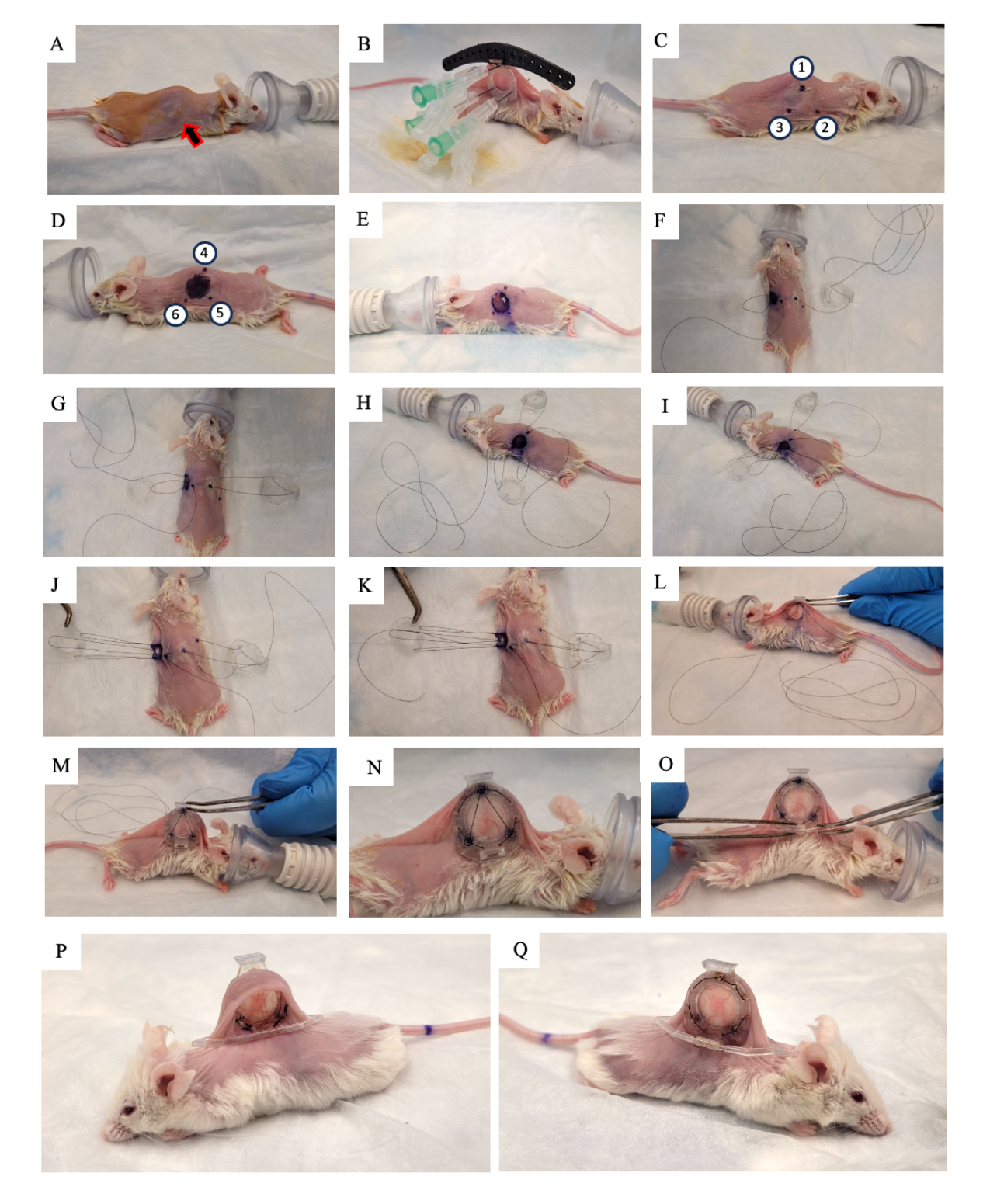
- Apply 10% povidone-iodine solution to the skin and allow it to air dry (Figure 2A).
- Replace the surgical mat with a new sterilized mat.
- Ensure that the mouse has reached the surgical plane of anesthesia using a toe pinch.
- Lift the skin of the mouse along the spine and look for the tumor growing on one of the two lateral skin folds. Place the back frame of the DSFC (Figure 2B) on the same side of the skin that the tumor is growing on, making sure to center the tumor in the frame.
- Add three sutures to each of the top three holes of the DSFC and the surgical guide to fix the position of the back frame (Figure 2B).
- Insert three needles through the back frame of the DSFC in the holes containing the spacers (Figure 2B).
NOTE: There are three 'spacers' on the back frame of the DSFC to maintain a gap between the front and back frames to ensure that blood flow is not restricted to the tissue inside the DSFC. The spacers are visible in Figure 1B. - Using a surgical marker, mark the six points where the DSFC back frame spacers will be located on both sides of the skin (points 1-6 in Figure 2C,D).
NOTE: The inserted needles should be used as a guide for the precise location of these points. - Draw a 1 cm diameter circle to indicate the skin that will be removed on the side opposite to the back frame (Figure 2D).
- Remove the needles and the back frame from the skin by cutting the sutures.
- Cut the 1 cm diameter hole in the skin that was marked in step 3.15 using surgical micro scissors (Figure 2E).
- Place the temporary suture to secure all parts of the window chamber to the skin. Insert a suture through point 4, through the top hole of the front frame of the DSFC, and then through point 1 on the opposite side of the mouse (Figure 2F and steps 1-2 in Supplementary Figure S1).
- Thread the suture through the top support post of the back frame and then back through the support post on the back frame that is closest to the head of the mouse (Figure 2F).
- Insert the suture through point 2. Then, thread the suture through the corresponding hole in the front frame (Figure 2G and step 3 in Supplementary Figure S1).
- From the inside of the skin, thread the suture through point 6 as indicated in Figure 2H and steps 3-4 in Supplementary Figure S1.
- Thread the suture through point 5 as indicated in Figure 2I and step 4 in Supplementary Figure S1.
- Bring the suture through the front frame, point 3, and then through the back frame as indicated in Figure 2J and step 5 in Supplementary Figure S1.
- Bring the suture back through point 1, the front frame of the DSFC, and then out through point 4 as indicated in Figure 2K and step 6 in Supplementary Figure S1.
- Tighten the entire assembly with this suture and slip the front frame underneath the skin through the hole that was created in step 3.17 (Figure 2L,M).
- Tie the two ends of this suture together and cut any excess string.
- Perform permanent sutures through the holes around the perimeter of the front and back frames of the DSFC. Suture the two frames together in the pattern shown in Figure 2N and Supplementary Figure S2.
- Cut and remove the temporary suture.
- Affix the support clip to the back frame of the DSFC by sliding it into the protrusion from the back frame (Figure 2O).
NOTE: An image of the mouse 2 weeks post surgery is shown in Figure 2P,Q. The support clip is used to keep the DSFC upright on the mouse to reduce skin tension and discomfort. - Administer 5 mg/kg body weight Meloxicam, a non-steroidal anti-inflammatory drug, subcutaneously for pain and inflammation reduction.
- Remove the mouse from anesthesia, wait until the mouse becomes ambulatory, and return it to its cage.
- Check on the mouse 2-3 h after surgery and then daily for at least 1 week. Consider the endpoint reached 2 months post window chamber surgery or if any of the conditions in step 2.17 are met (whichever occurs first).

Figure 2: DSFC surgery procedure. (A) The mouse is prepared for surgery by removing the hair and disinfecting the skin. The subcutaneous tumor is indicated by the arrow. (B) The back frame is placed in the appropriate position and secured by three syringes as well as temporary sutures affixed to the black surgical guide. (C,D) The spacer locations (points 1-6) and hole are marked on both sides of the skin. (E) The skin is removed. (F-K) A temporary suture is threaded through the two layers of skin, front, and back frames of the DSFC to secure all the parts together. (L,M) The temporary suture is tightened, and the front frame is inserted underneath the skin. (N) Eight permanent sutures are placed to secure the DSFC. (O) Finally, the temporary suture is removed, and the support clip is attached. (P,Q) The same mouse is shown 2 weeks after surgery from both sides. Abbreviation: DSFC = dorsal skinfold window chamber. Please click here to view a larger version of this figure.
4. Optical imaging
- Allow the mouse to heal and the inflammation to decrease for at least 5 days after surgery before imaging.
- Anesthetize the mouse using 5% isoflurane for induction and 2% isoflurane for maintenance (oxygen flow rate set to 0.5 L/min).
- Apply veterinary eye lubricant to prevent dryness. Reapply every 30 min or as needed.
- Secure the mouse in an imaging stage with a gas anesthesia attachment as shown in Supplementary Figure S3.
- Obtain a wide field of view (>1.5 cm width) brightfield microscopy image. Ensure that the fiducial marker divots on the front frame of the DSFC are visible.
NOTE: There are seven divots around the perimeter of the glass on the front frame that align with the seven fiducial marker wells on the fiducial marker ring attachment. These divots are visible in Figure 1A. - On the same day, obtain a microvascular image using the intravital microscopy modality of choice. Use the same imaging stage from step 4.4 (Supplementary Figure S3) for this. Remove the mouse from anesthesia, wait until the mouse becomes ambulatory, and return it to its cage.
NOTE: We use speckle variance optical coherence tomography (svOCT) for high-resolution 3D microvascular images.
5. Magnetic resonance imaging
- Place the mouse cage under a heat lamp to warm the mice for approximately 15 min before anesthetizing the mouse.
NOTE: Warming promotes vasodilation, which will aid in tail vein catheter placement. - Anesthetize the mouse using 5% isoflurane for induction and 2% isoflurane for maintenance (oxygen flow rate set to 0.5 L/min).
- Record the weight of the mouse using an electronic scale for correct drug dosing.
NOTE: For accurate body weight measurements, make sure to subtract the weight of the DSFC assembly (0.83 g). - Place the mouse on the MRI bed and apply veterinary eye lubricant to prevent dryness.
- Maintain the body temperature of the mouse using a water heater and pump system.
- Position a respiratory monitoring pillow underneath the diaphragm of the mouse and maintain at 30 ± 5 breaths/min.
- If using a contrast agent, insert a 27 G butterfly needle into the tail vein with microtubing attached (30 μL of dead volume prefilled with 1% herapin-saline solution). Secure the needle and microtubing to the MRI bed with surgical tape.
- Secure the window chamber in a 3D printed 'immobilization device' as shown in Figure 3.
- Using an 18 G needle, inject veterinary eye lubricant into the seven tubes on the MRI fiducial marker.
- Affix the fiducial marker to the DSFC by aligning the three square connectors to the three posts protruding from the front frame (Figure 3).
- Connect the tail vein catheter to the drug delivery line and syringe in the automatic pump. Insert the bed into a 7-tesla preclinical MRI scanner.
- Acquire coronal and axial T2-weighted (T2w) image sets to visualize the plane of the window chamber (echo time TE = 25 ms; repetition time TR = 2,500 ms; 40 x 40 mm field-of-view with a 64 x 64 matrix for 0.5 x 0.5 mm in-plane resolution; 0.5 mm slice thickness; 25 s). Prescribe a sagittal T2-weighted set (TE = 25 ms; TR = 2,500 ms; 32 x 32 mm field-of-view with 128 x 128 matrix for 0.25 x 0.25 mm in-plane resolution; at least 11 imaging slices; 0.5 mm slice thickness; 87 s), which is then rotated into the plane of the DSFC and fiducial markers, based on the coronal and axial views, as shown in Figure 4. Iteratively re-orient and position the sagittal set until the imaging slices are fully aligned so that slice 5 fully contains tissue signal in the DSFC and slice 6 contains no tissue signal in the DSFC.
- Perform microvascular imaging using the microvascular MRI method of choice.
NOTE: For the microvascular MR acquisitions, the fiducial marker slices do not need to be imaged since the images are acquired in the same imaging frame-of-reference as the T2w registration images.- Acquire all acquisitions detailed in steps 5.12 and 5.13 over a 32 x 32 mm field-of-view with a 64 x 64 matrix for 0.5 x 0.5 mm in-plane resolution. For all MRI acquisitions, use consistent RF pulses to improve through-plane geometric consistency (sinc excitation; sinc3 refocusing; 2,484 Hz bandwidth).
- For DCE imaging:
- If measurements of gadolinium concentration are desired, obtain T1 maps using 2D-RARE images acquired at variable repetition times (TE = 7 ms; RARE factor = 2; TR = 350, 500, 750, 1,000, 1,500, 2,500, and 4,000 ms; 8 min 28 s).
- Perform time-series imaging using 2D RARE images (TE = 8.1 ms; RARE factor = 2; TR = 200 ms; flip angle = 90°; temporal resolution = 12.8 s; 188 repetitions; total monitoring time = 40 min 6 s).
- Inject 0.75 mmol/kg body weight Gadobutrol over 10 s via the tail vein after completion of five image repetitions using an automated MR-compatible syringe pump.
- For IVIM MRI:
- Perform diffusion-weighted imaging with the following B-values: 0, 20, 40, 60, 80, 100, 150, 200, 400, 600, 800, 1,000 s/mm2 with three averages of the B = 0 s/mm2 and isotropic sampling (TE = 16 ms; TR = 800 ms; gradient duration = 2.2 ms; gradient separation = 9 ms; 61 min).
NOTE: Diffusion-weighted imaging is acquired using a 2D Fourier transform readout, rather than with distortion-prone echo-planar imaging, to ensure geometric consistency of the tumor and surrounding tissue signals within the DSFC across the image sets and with the intravital microscopy images.
- Perform diffusion-weighted imaging with the following B-values: 0, 20, 40, 60, 80, 100, 150, 200, 400, 600, 800, 1,000 s/mm2 with three averages of the B = 0 s/mm2 and isotropic sampling (TE = 16 ms; TR = 800 ms; gradient duration = 2.2 ms; gradient separation = 9 ms; 61 min).
- Remove the mouse from anesthesia, wait until the mouse becomes ambulatory, and return it to its cage.

Figure 3: DSFC MR imaging setup. (A) Side and (B) top views of the mouse positioned on the MRI bed with DSFC secured and immobilized. The mouse has a tail vein catheter for contrast agent injection and the fiducial maker ring is affixed to the front frame of the DSFC. Abbreviations: DSFC = dorsal skinfold window chamber; MR = magnetic resonance imaging. Please click here to view a larger version of this figure.

Figure 4: MRI slice locations with respect to fiducial markers and window chamber. (A) A diagram of the DSFC with fiducial marker ring attachment with the 11 overlaid MRI slices. Several T2-weighted images must be acquired to ensure that the slices are correctly aligned with the DSFC and tissue. (B,C) Correct positioning of the 11 slices with respect to the tissue in the DSFC from different orientations. (D) Slice 5 is the most superficial slice where intermodality correlation analysis will be performed. (E) Slice 6 contains no tissue signal indicating that it is properly aligned with the DSFC. (F) Finally, the 7 fiducial markers are clearly visible in slice 9. Scale bars = 5 mm. An 'X' on the axis indicates that the axis is going into the page and a circle indicates that the axis is coming out of the page. Abbreviations: DSFC = dorsal skinfold window chamber; MRI = magnetic resonance imaging. Please click here to view a larger version of this figure.
6. MRI to intravital microscopy co-registration
- In MATLAB, open the Multimodal_Image_Register.m file contained in Supplementary File 2.
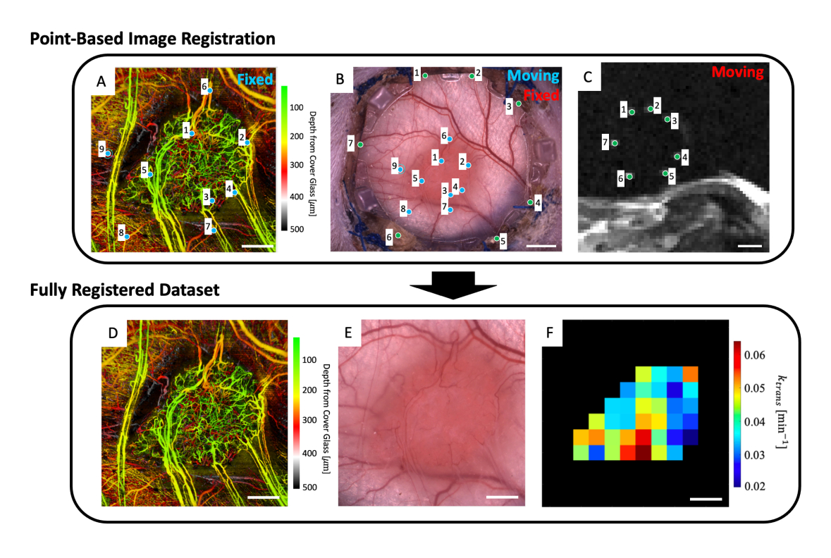
- To the workspace, load in the microvascular image (Figure 5A), brightfield microscopy image (Figure 5B), and microvascular MRI data (IVIM and/or DCE MRI parameter maps).
- Click the Run button.
- Using the pop-up file finder, navigate to the file containing the T2w MRI slices.
- Select up to four T2w MRI slices that clearly display the fiducial markers (Figure 5C).
- A user interface showing the microscopy image (Figure 5B) and the depth-averaged T2w MRI slices (Figure 5C) will be displayed. Place a point on each of the seven fiducial markers in the MRI image and match them to their corresponding point on the microscopy image (fiducial marker divots around the perimeter of the glass on the front frame of the DSFC) as indicated by the green points in Figure 5B,C.
- Close the window.
- A figure containing the overlaid MRI and microscopy images will appear to help with assessing the quality of the registration between the two datasets. If the registration is adequate, continue the code by typing y, then pressing enter in the command window. Otherwise, retry this step by typing n in the command window and pressing enter.
NOTE: Successful co-registration of the MRI dataset with the microscopy image means that the seven bright fiducial markers from the MRI dataset are centered and fully contained within their corresponding divots on the front frame of the DSFC. - A user interface showing the microscopy image (Figure 5B) and the svOCT microvascular imaging dataset (Figure 5A) will be displayed. Select at least three microvascular landmark points on the svOCT microvascular image and the corresponding points in the microscopy image as indicated by the blue points in Figure 5A,B.
- Close the window.
- A figure containing the overlaid svOCT and microscopy images will appear to help with assessing the quality of the co-registration between the two datasets. If the registration is adequate, continue the code by typing y, then pressing enter in the command window. Otherwise, retry this step by typing n in the command window and pressing enter.
NOTE: Successful co-registration of the svOCT dataset with the microscopy image means that the vessels from both datasets are perfectly overlaid with each other. - Close the window.
- The co-registered microcopy image will then appear. Contour the tumor in this image.
- Close the window.
- Several figures will then be displayed: the svOCT microvascular dataset (Figure 5D), the co-registered microscopy image (Figure 5E), and the co-registered MRI parameter maps (Figure 5F). Save the maps for later analysis.
NOTE: The displayed MRI maps are restricted to the user-drawn tumor contour (Figure 5F).

Figure 5: Multimodal point-based co-registration. (A) Color depth-encoded microvascular svOCT dataset; scale bar = 1 mm. (B) Brightfield microscopy image of the window chamber; scale bar = 2 mm. (C) Average of T2w MRI slices 8-11 showing the seven fiducial markers contained in the fiducial marker ring; scale bar = 5 mm. (C) First, the 'moving' T2w MRI dataset is co-registered to the 'fixed' brightfield microscopy image using the user-inputted green markers on both image sets. Next, the 'moving' brightfield microscopy image and co-registered MRI image are co-registered to the 'fixed svOCT dataset' using the blue markers in A and B. The final co-registered dataset includes the (D) svOCT, (E) brightfield microscopy image, and (F) functional MRI parameter map. The black voxels in F are outside of the tumor and are therefore not considered in the analysis. For D-F, scale bar = 1 mm. Abbreviations: svOCT = speckle variance optical coherence tomography; MRI = magnetic resonance imaging. Please click here to view a larger version of this figure.
Results
Speckle variance optical coherence tomography (svOCT) was performed to obtain large field-of-view (FOV) 3D microvascular images (6 x 6 mm2 lateral x 1 mm depth). To obtain these images, a previously described swept source OCT system based on a quadrature interferometer was used23. OCT images were acquired by stitching together two laterally adjacent 3 x 6 mm2 FOV scans. Each B-scan consisted of 400 A-scans and was performed 24x per location (25 ms apart) to enable accurate sp...
Discussion
In this work, we have developed a workflow to perform both intravital microscopy and clinically applicable imaging (CT, MRI, and PET) in the same animal. This was done with the goal of translating preclinical microscopy findings to the clinic by direct correlation of intravital microscopy with clinical imaging modalities such as MRI. Although conventional DSFC designs are made of metal2,3, we have adapted the DSFC to be MR-compatible by using 3D-printed window ch...
Disclosures
The authors have no conflicts of interest to disclose.
Acknowledgements
We thank Dr. Carla Calçada (Postdoctoral Fellow, Princess Margaret Cancer Centre) and Dr. Timothy Samuel (Ph.D. Student, Princess Margaret Cancer Centre) for help with tumor cell culturing and inoculation protocol development. Dr. Kathleen Ma, Dr. Anna Pietraszek, and Dr. Alyssa Goldstein (Animal Research Centre, Princess Margaret Cancer Centre) helped with surgery protocol development. Jacob Broske (Medical Engineering Technologist, Princess Margaret Cancer Centre) and Wayne Keller (Hardware Client Executive, Javelin Technologies – A TriMech Group Company) 3D printed the window chambers. James Jonkman (Advanced Optical Microscopy Facility, University Health Network) provided valuable guidance for brightfield and fluorescence microscopy image acquisition.
Materials
| Name | Company | Catalog Number | Comments |
| Cell Culture Materials | |||
| BxPC-3 Human Pancreatic Cancer Cells | ATCC (American Type Culture Collection) | CRL-1687 | |
| Corning Matrigel Basement Membrane Matrix, LDEV-free, 10 mL | Corning | 354234 | |
| Corning Stripettor Ultra Pipet Controller | Corning | 07-202-350 | |
| Dulbecco Phospphate buffered saline without Calcium, Magnesium, or phenol red, 500 mL | Gibco | 14190144 | |
| Fetal Bovine Serum (Canada), 500 mL | Sigma-Aldrich | F1051-500ML | |
| Penicillin-Streptomycin 100x (liquid,stabilized, sterile-filtered, cell culture tested) | Sigma-Aldrich | P4333-100ML | |
| RPMI Medium 1640 (1x), liquid; with L-Glutamine, 500 mL | Gibco | 11875093 | |
| TrypLE Express Enzyme, 500 mL | Gibco | 12605028 | |
| Window Chamber Materials | |||
| 12 mm Glass Coverslip | Harvard Apparatus | CS-12R No. 1.5 | |
| Connex 500 3D Printer | Stratasys | N/A | |
| Biocompatible clear MED610 resin | Stratasys | RGD810 | |
| Loctite AA 3105 UV curable glue | Loctite | LCT1214249 | |
| Window chamber back frame | Trimech Inc | N/A | |
| Window chamber fiducial marker | Trimech Inc | N/A | |
| Window Chamber front frame | Trimech Inc | N/A | |
| Window chamber support clip | Trimech Inc | N/A | |
| inoculation and Surgery Materials | |||
| BD SafetyGlide Insulin Syringes with Permanently Attached Needles, 0.5 mL, 29 G x 1/2" | BD | CABD305932 | |
| Betadine Solution | Betadine | AP-B002C2R98U | |
| Cidex OPA 14 Day Solution 3.8 L | ASP | JOH20394 | |
| Disposable Surgical Underpads 23 inch x 24 inch | Kendall | 7134 | |
| Eye lubricant | Optixcare | 50-218-8442 | |
| Hair removal cream | Nair | 061700222611 | |
| Halstead Hemostatic Forceps | Almedic | 7742-A12-150 | |
| Heating pad | Sunbeam | B086MCN59R | |
| Iris Scissors | Almedic | 7601-A8-690 | |
| Isoflurane | Sigma | 792632 | |
| Metacam | Boehringer Ingelheim Animal Health USA Inc | NDC 0010-6015-03 | |
| NOD.Cg-Rag1tm1Mom Il2rgtm1Wjl/SzJ mouse | the Jackson laboratory | 7799 | |
| Peanut Clipper & Trimmer | Wahl | 8655-200 | |
| SOFSILK Nonabsorbable Surgical Suture #5-0 with 3/8" Taper point needle (17 mm) (Wax Coated,Braided Black Silk, Sterile) | Syneture | VS880 | |
| Splinter Forceps | Almedic | 7725-A10-634 | |
| MR Imaging | |||
| 3D printed window chamber immobilization device. | custom 3D printed, refer to figure 3 for details. | ||
| Convection heating device | 3M Bair Hugger | 70200791401 | |
| Drug injection system | Harvard Apparatus | PY2 70-2131 | PHD 22/2200 MRI compatible Syringe Pump |
| Gadovist 1.0 | Bayer | 2241089 | |
| Respiratory monitoring system | SAII | Model 1030 | MR-compatible monitoring and gating system for small animals. |
| Tail vein catheter (27 G 0.5" ) | Terumo Medical Corp | 15253 | |
| Optical Imaging | |||
| 3D printed imaging stage | Custom 3D printed, refer to supplementary figure 3 for details. | ||
| 12 V 7 W Flexible Polyimide Heater Plate Thin Adhesive PI Heating Film 25 mm x 50 mm | BANRIA | B09X16XCVS | Heating element used for mouse body temeprature regulation. |
| DC power supply | BK Precission | 1761 | Used to power the heating element. |
| Leica MZ FLIII | Leica Microsystems | 15209 | |
| svOCT imaging system | In-house made imaging system. Details can be found in reference 23. | ||
| Software | |||
| MATLAB Software | MathWorks | R2020A |
References
- Fukumura, D., Duda, D. G., Munn, L. L., Jain, R. K. Tumor microvasculature and microenvironment: Novel insights through intravital imaging in pre-clinical models. Microcirculation. 17 (3), 206-225 (2010).
- Demidov, V., et al. Preclinical longitudinal imaging of tumor microvascular radiobiological response with functional optical coherence tomography. Sci Rep. 8 (1), 38 (2018).
- Alieva, M., Ritsma, L., Giedt, R. J., Weissleder, R., van Rheenen, J. Imaging windows for long-term intravital imaging. IntraVital. 3 (2), e29917 (2014).
- Dreher, M. R., et al. Tumor vascular permeability, accumulation, and penetration of macromolecular drug carriers. J Natl Cancer Inst. 98 (5), 335-344 (2006).
- Momiyama, M., et al. Subcellular real-time imaging of the efficacy of temozolomide on cancer cells in the brain of live mice. Anticancer Res. 33 (1), 103-106 (2013).
- Dadgar, S., Rajaram, N. Optical imaging approaches to investigating radiation resistance. Front Oncol. 9, 1152 (2019).
- Fukumura, D., Jain, R. K. Tumor microvasculature and microenvironment: Targets for anti-angiogenesis and normalization. Microvasc Res. 74 (2-3), 72-84 (2007).
- Dirkx, A. E. M., et al. Anti-angiogenesis therapy can overcome endothelial cell anergy and promote leukocyte-endothelium interactions and infiltration in tumors. FASEB J. 20 (6), 621-630 (2006).
- Allam, N., et al. Longitudinal in-vivo quantification of tumour microvascular heterogeneity by optical coherence angiography in pre-clinical radiation therapy. Sci Rep. 12, 6140 (2022).
- Stadlbauer, A., et al. Tissue hypoxia and alterations in microvascular architecture predict glioblastoma recurrence in humans. Clin Cancer Res. 27 (6), 1641-1649 (2021).
- Danquah, M. K., Zhang, X. A., Mahato, R. I. Extravasation of polymeric nanomedicines across tumor vasculature. Adv Drug Deliv Rev. 63 (8), 623-639 (2011).
- Bentzen, S. M., Gregoire, V. Molecular imaging-based dose painting: a novel paradigm for radiation therapy prescription. Semin Radiat Oncol. 21 (2), 101-110 (2011).
- Gabriel, E. M., Fisher, D. T., Evans, S., Takabe, K., Skitzki, J. J. Intravital microscopy in the study of the tumor microenvironment: from bench to human application. Oncotarget. 9 (28), 20165-20178 (2018).
- Demidov, V., et al. Preclinical quantitative in-vivo assessment of skin tissue vascularity in radiation-induced fibrosis with optical coherence tomography. J Biomed Opt. 23 (10), 1-9 (2018).
- Wallace, M. B., et al. The safety of intravenous fluorescein for confocal laser endomicroscopy in the gastrointestinal tract. Aliment Pharmacol Ther. 31 (5), 548-552 (2010).
- Standish, B. A., et al. In vivo endoscopic multi-beam optical coherence tomography. Phys Med Biol. 55 (3), 615-622 (2010).
- Wang, J. H., et al. Dynamic CT evaluation of tumor vascularity in renal cell carcinoma. AJR Am J Roentgenol. 186 (5), 1423-1430 (2006).
- Tropres, I., et al. Imaging the microvessel caliber and density: Principles and applications of microvascular MRI. Magn Reson Med. 73 (1), 325-341 (2014).
- McDonald, D. M., Choyke, P. L. Imaging of angiogenesis: from microscope to clinic. Nat Med. 9, 713-725 (2003).
- O'Connor, J. P. B., et al. Dynamic contrast-enhanced imaging techniques: CT and MRI. Brit J Radiol. 84, S112-S120 (2011).
- Lima, M., Le Bihan, D. Clinical intravoxel incoherent motion and diffusion MR imaging: past, present, and future. Radiology. 278 (1), 13-32 (2015).
- Zabel, W. J., et al. Bridging the macro to micro resolution gap with angiographic optical coherence tomography and dynamic contrast enhanced MRI. Sci Rep. 12 (1), 3159 (2022).
- Mao, Y., Flueraru, C., Chang, S., Popescu, D. P., Sowa, M. G. High-quality tissue imaging using a catheter-based swept-source optical coherence tomography systems with an integrated semiconductor optical amplifier. IEEE Trans Instrum Meas. 60 (10), 3376-3383 (2011).
- Mariampillai, A., et al. Optimized speckle variance OCT imaging of microvasculature. Opt Lett. 35 (8), 1257-1259 (2010).
- Tofts, P. S., et al. Estimating kinetic parameters from dynamic contrast-enhanced T1-weighted MRI of a diffusible tracer: standardized quantities and symbols. J Magn Res Imaging. 10 (3), 223-232 (1999).
- Khalifa, F., et al. Models and methods for analyzing DCE-MRI: a review. Med Phys. 41 (12), 124301 (2014).
- Reitan, N. K., Thuen, M., Goa, P. E., de Lange Davies, C. Characterization of tumor microvascular structure and permeability: comparison between magnetic resonance imaging and intravital confocal imaging. J Biomed Opt. 15 (3), 036004 (2010).
- Dhani, N. C., et al. Analysis of the intra- and intertumoral heterogeneity of hypoxia in pancreatic cancer patients receiving the nitroimidazole tracer pimonidazole. Br J Cancer. 113 (6), 864-871 (2015).
- Gaustad, J. V., Brurberg, K. G., Simonsen, T. G., Mollatt, C. S., Rofstad, E. K. Tumor vascularity assessed by magnetic resonance imaging and intravital microscopy imaging. Neoplasia. 10 (4), 354-362 (2008).
- Rouffiac, V., et al. Multimodal imaging for tumour characterization from micro to macroscopic level using a newly developed dorsal chamber designed for long-term follow-up. J Biophotonics. 13 (1), 201900217 (2020).
- Leung, H. M., Schafer, R., Pagel, M. M., Robey, I. F., Gmitro, A. F. Multimodality pH imaging in a mouse dorsal skin fold window chamber model. Proc SPIE Int Soc Opt Eng. 8574, 85740L (2013).
- Erten, A., et al. Magnetic resonance and fluorescence imaging of doxorubicin-loaded nanoparticles using a novel in vivo model. Nanomed. 6 (6), 797-807 (2010).
- Maeda, A., DaCosta, R. S. Optimization of the dorsal skinfold window chamber model and multi-parametric characterization of tumor-associated vasculature. Intravital. 3 (1), e27935 (2014).
- Allam, N., Taylor, E., Vitkin, I. A. Low-cost 3D-printed tools towards robust longitudinal multi-modal pre-clinical imaging. bioRxiv. , (2023).
- Alexander, S., Weigelin, B., Winkler, F., Friedl, P. Preclinical intravital microscopy of the tumour-stroma interface: invasion, metastasis, and therapy response. Curr Opin Cell Biol. 25 (5), 659-671 (2013).
- Steven, A. J., Zhuo, J., Melhem, E. R. Diffusion kurtosis imaging: an emerging technique for evaluating the microstructural environment of the brain.Am. J Roentgenol. 202 (1), W26-W33 (2014).
- Mayer, P., et al. Diffusion kurtosis imaging-a superior approach to assess tumor-stroma ratio in pancreatic ductal adenocarcinoma. Cancers (Basel). 12 (6), 1656 (2020).
Reprints and Permissions
Request permission to reuse the text or figures of this JoVE article
Request PermissionThis article has been published
Video Coming Soon
Copyright © 2025 MyJoVE Corporation. All rights reserved