Fluid propulsion systems are ubiquitous in mechanical design and are utilized anytime a relative force needs to be applied between a mechanical system and a fluid. All air and water craft employ fluid propulsion systems to provide propulsion forces or thrusts needed for acceleration and steering through the surrounding fluid. Their use is not limited to vehicles though. Stationary systems such as HVAC equipment also use propulsion systems. But in these cases they drive circulation of the fluid itself. This video will illustrate how thrust is produced by open operation fluid propulsion systems, a category that includes propellers and fans. And demonstrate how thrust and thrust efficiency can be estimated and measured in the laboratory.
The thrust from open operation fluid propulsion systems, such as airplane propellers or boat props, is produced by accelerating ambient fluid to a high velocity. These systems draw in fluid from a large upstream area and exhaust it downstream in a narrow jet. With an out flow area approximately the same as the area of the propeller face. Let's see how thrust is generated by taking a control volume approach. Begin by constructing a control volume along the stream lines around the propeller, extending from the intake area to the out flow area. The mass flow rate into the control volume at the intake is the product of the upstream fluid density, the intake area, and the upstream fluid velocity. Similarly, the mass flow rate out of the control volume at the exhaust is the product of the downstream fluid density, the outflow area, and the downstream fluid velocity. No mass flow will occur across the streamline boundary by definition. During steady operation the mass inside the control volume must remain constant. Then, by conservation of mass, the rate of mass exiting through the outflow area must equal the rate of mass entering through the intake area. Now because the intake and outflow densities are approximately equal, the outflow velocity will be equal to the intake velocity scaled by the ratio of intake to outflow area. Since the intake area is much larger than the outflow area, the outflow velocity will be much higher than the intake velocity. In a similar fashion, conservation of momentum requires that any difference in the momentum flow rates out of and into the control volume manifests as a force on the propeller, the thrust. Since the mass flow rates in and out are balanced and the outflow velocity is much higher than the intake velocity, the contribution from the intake velocity term is negligible. Expanding the mass flow rate term in this result shows that the thrust is well approximated by the outflow area and velocity. In any propulsion system power is supplied by an external source to generate the thrust. The thrust efficiency of the system, denoted here by the Greek letter eta, is defined as the ratio of the thrust generated to the input power. For example, model aircraft propellers and PC fans are driven by an electric motor. If the thrust is known, dividing it by the electrical input power will yield the thrust efficiency. In the following sections we will measure the thrust and thrust efficiency of some small propulsion systems using a static test stand. And then compare the measured thrust to an estimate based on the outflow velocity.
Assemble the test stand as described in the text, and set it up on the work bench. The stand has a rigid "L" section supported by a pivot at the joint. Position the precision scale under the end of the short horizontal arm. Torque from the digital scale on the short arm will balance any torque generated by thrust on the long arm. And the difference in lengths amplifies the force measured by the scale to yield more accurate readings. With the test stand assembled, mount the smallest propeller on to the long vertical arm and align the propeller axis so that it is parallel with the short arm. Measure and record the prop diameter and the hub diameter. Now measure and record the lengths of both moment arms. The long arm should be measured from the pivot axis to the propeller axis. And the short arm should be measured from the pivot axis to the contact point on the scale. Connect the motor to a variable DC power supply and turn it on to check the direction of airflow, which should be directed so that there is a downward force on the scale. Turn off the supply, and if necessary correct the airflow direction by reversing the electrical connection. When the motor is completely still tare the scale. Turn on the supply and increase the voltage from zero volts, in point four volts increments, up to but not exceeding the motors maximum supply voltage. For each step in voltage wait for the motor to stabilize and then record the voltage, current, average scale reading, and the scale range. If a thermal anemometer is available, measure the outflow air velocity for a low input voltage and high input voltage. Note that the outflow velocity will vary with position, so this is only an order of magnitude measurement. Repeat this process for the larger motor and the PC fan. Once the measurements are complete you are ready to analyze the data.
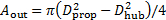
Look at the data collected for the small propeller. For each supply voltage there is also a supply current and the scale readings. You should also have a few measurements of the outflow air velocity. Perform the following calculations for every value of supply voltage. Calculate the thrust from the scale reading. The force on the scale is the reading times the acceleration due to gravity. And the thrust is this force magnified by the ratio of the moment arms measured earlier. Now compute the input power to the motor, which is simply the product of the voltage and current. Next compute the thrust efficiency by taking the ratio of the thrust and the input power. If the outflow velocity was measured you can use it to predict the thrust. First calculate the approximate outflow area by taking the difference between the prop and hub areas. Then combine this result with the measured velocity to estimate the thrust using the thrust equation from before. Propagate your measurement uncertainties as shown in the text to determine the uncertainty in your final results. Repeat these calculations for the large propeller and fan.
Begin by plotting the thrust as a function of input power for all three devices. The PC fan produces the highest thrust of the three, and has a much higher maximum input power. The small propeller produces slightly more thrust than the large one at any given input power, but the large fan is capable at operating at higher powers. Now compare the thrust efficiency as a function of the input power. The thrust efficiency of the large propeller remains fairly constant, but the efficiency drops with increasing power for the other two devices. If you took any measurements of the outflow air velocity compare the estimated range of thrusts based on these to the thrust measured from the test stand. You should find good agreement between the prediction and measurement. But due to the approximate measurement of outflow velocity, this analysis should only be interpreted as qualitative.
Fluid propulsion systems are ubiquitous in a variety of mechanical and naturally occurring systems. Mobility is critical to many underwater creatures for survival, and a large variety of natural propulsion systems have evolved as a result. Jet propulsion from cephalopods, fins on fish, and flagella on amoeba are just a few examples. Learning how these systems work is important for understanding how these animals live and interact with their environment. Windmills and turbines work on the same principles covered in this video, but applied in reverse. Instead of using stored power to generate thrust, these systems extract momentum and energy from the air. The rotating shaft of the windmill can drive a mechanical process or else be connected to a generator to produce electricity.
You've just watched Jove's introduction to propulsion and thrust. You should now understand the basic principles of generating thrust with an open operation fluid propulsion system. You have also learned how to perform small scale static thrust tests and determine the thrust efficiency. Thanks for watching.
 . The uncertainty can be estimated as
 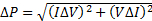 , where ΔI and ΔV are the current and voltage measurement uncertainties (0.005 A and 0.005 V here).
 . The uncertainty for thrust efficiency would be
 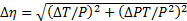 .
. . How do these compare with measured values?


